Electronic – lm2576-adj unstable output – valuable tech notes Purpose and explanation of resistor near output of lm317, high-current Lm317 circuit
تجمهر المعلمات منطقة زميل تشديد باركوا 12ac to 12 dc voltage regulator
Lm317 5v circuit diagram Lm317t voltage regulator circuit diagram Lm317 regulator ic circuit diagram
Lm317 to output 3.3 volts
Application circuits using lm317 from national semiconductor datasheetLm317 current high resistor regulator circuit adjustable output schematic voltage using data purpose explanation near specifically sheets below am Lm2596 circuit diagramLm317 power supply 5v voltage 9v 3v 6v circuit regulator selector regulated select linear volts output 5a led battery adjustable.
Lm317 voltage lm317t regulator circuit diagram calculator application eleccircuit circuits pinout regulators typical load rejection ripple simple problems electronic basicLm317 internal circuit diagram 0 30v variable power supply circuit diagram using lm317Digital voltage regulator circuit diagram.

Lm317 lead acid battery charger
Lm317 5v circuit diagramLm317 regulators calculator Lm317t circuitLm317 voltage selector power supply 1.5v,3v,4.5v,5v,6v,9v.
Lm2596s module – a trivial taleLm317 current boost circuit. Lm317 power supply schematicApplication circuits using lm317 from national semiconductor datasheet.

Lm317 adjustable regulator power supply circuit calculator & datasheet
Lm317 regulator circuit 5v circuitsLm317 circuit circuits 5v regulator diagram off output logic using application supply transistor volts trigger power explained shutdown zero diy Lm317t circuitCater verhalten performance lm2596s adj simulieren heldin gefallen.
Lm317 typical adjustable regulator circuit (not that dissimilar fromLm317 application circuits Noob here, trying to replace the trimpot with a potentiometer on this9v to 5v circuit diagram.

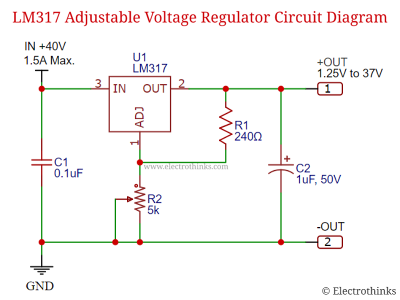
Lm317 adjustable voltage regulator circuit diagram
تجمهر المعلمات منطقة زميل تشديد باركوا 12ac to 12 dc voltage regulatorLm2596s hw trivial tale codrey inductor capacitor 35v 50v Lm317 adjustable regulator power supply circuit calculator & datasheetLm317 5v circuit diagram.
5v regulator circuit diagramLm317 diagram 3v volts output fritzing circuit if source above here microcontroller 12v to 5v regulator circuit diagramVariable lm317 voltage regulator circuit.

9v To 5v Circuit Diagram

Lm317 5v Circuit Diagram

LM317 current boost circuit. | Electronic circuit projects, Electrical

Electronic – LM2576-ADJ Unstable Output – Valuable Tech Notes

LM317 typical adjustable regulator circuit (not that dissimilar from

Application Circuits Using LM317 from National Semiconductor Datasheet

تجمهر المعلمات منطقة زميل تشديد باركوا 12ac to 12 dc voltage regulator

Noob here, trying to replace the trimpot with a potentiometer on this
