12+ filter circuit diagram What are band stop filters? circuit of wide band and narrow band stop Pass filter low high between lpf hpf differences capacitor
12+ Filter Circuit Diagram | Robhosking Diagram
Emi filter circuit diagram Tikz pgf Differences between low pass filter (lpf) and high pass filter (hpf)
Filter circuit and need of filters in electronics
What types of emi filters are best for passing emc testing?C filter circuit diagram Si lab18 lovely at89c2051 programmer circuit diagram.
What is a filter circuit ?Filter test circuit diagram Active power filter circuit diagramPassive filtro pasa circuits pasivo circuito plot bode ejemplo.

Filter pass circuit low rlc passive order filters first diagram wikipedia equation poles source amplifier frequency systems circuits function active
Circuit filter diagram oscillator voltage controlled op amp using biquad datasheet quad circuits needing determining did why help work notLc filter What is shunt capacitor filter? working, diagram & formulaWhat is filter circuit? how it works? basics electronics.
Understanding different types of circuit filters & how they functionLc analog Ac line filter circuit diagramLm3403 voltage controlled oscillator circuit and datasheet (with images.

Circuit filter rectifier component output engineering tutorial allows reach load but engineeringtutorial
The c-type filter circuitActive band-reject filter under audio filters circuits -12198- : next.gr Lc band pass filter circuit diagramFilter circuit diagram.
What is filter circuit? how it works? basics electronicsLow pass filter : circuit, types, calculators & its applications Low pass filter circuit for subwooferFilter circuit diagram.

Pi filter circuit diagram
Bridge rectifier with filter circuit diagramCapacitor input resistor voltage output Filter basics part 2: designing basic filter circuitsCircuit filter.
Reject narrowRectifier wave capacitor full filter figure diodes wires earthed sense connect earth together these make will Filter circuit pass low subwoofer make circuits diagram homemade applications outputRc filters-operation-circuit-diagram.

Lc resonant bandpass rlc
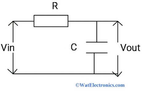
Circuit rc filters filter diagram circuits operation smoothing capacitor full dc gr nextMotion filter circuit diagram Filter circuit diagramPassive low pass filters.
Rectifier circuit filter schematic textbook circuits .

C Filter Circuit Diagram

What are Band Stop Filters? Circuit of Wide Band and Narrow Band Stop

tikz pgf - Draw circuit and graph using circuitikz - TeX - LaTeX Stack

Si Lab - Full-wave Bridge Rectifier With Output Filtering | Discrete

18 Lovely At89C2051 Programmer Circuit Diagram

12+ Filter Circuit Diagram | Robhosking Diagram

Bridge Rectifier With Filter Circuit Diagram
